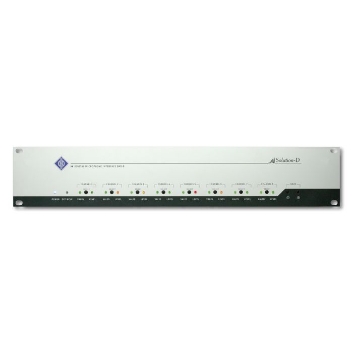
Neumann DMI-8 - EU
by Neumann- Installment Payment You can pay in installments using Visa, Visa Premium, Maestro, MasterCard, Diners credit cards. The fee is 5% over the quoted price, and it is assigned to your purchase order in your shopping cart upon the selection of the methods of payment. For more details, please click on the link containing The Methods of Payment.
- Fast Delivery For all the purchase orders within Croatia received by 02:00 p.m. on a working day, delivery will be made on the following working day*. On the territory of Europe, we provide a fast delivery service. For more details, please click on the link containing The Delivery Terms.
- International Purchasing The companies within the EU (except for the Republic of Croatia) with a valid VAT ID number, will pay the price exclusive of VAT. The price will be calculated upon checkout. All the customers outside of the EU will pay the export price exclusive of VAT.
Package includes
- 1 x Neumann DMI-8 - EU
Equipment that supports the AES 42 standard can process the output signals of Solution-D microphones directly. In all other cases, the DMI-2 portable or DMI-8 digital microphone interface is used. The DMIs convert the AES 42 data format supplied by the microphone into an AES/EBU signal.
The Interface is operated and the microphone parameters are controlled via the Neumann RCS remote control software, which is installed on a desktop or laptop computer. The computer is connected to the DMI via a USB port and a USB to RS 485 interface converter. If a large number of microphones is used, several DMI-8's can be cascaded. In this case, each digital microphone interface can be addressed individually.
In addition to a word clock input and output, the DMIs also have an internal word clock generator. If no master word clock signal (e.g. from a mixing console) is present at the input, the DMI internal word clock is used automatically to synchronize the microphone channels, and the signal is switched to the word clock output.
External commands such as "On Air" (red light) can be controlled via a 9-pin user port.
The DMI-8
The DMI-8, an eight-channel version of the digital microphone interface is considerably simplifying the setup for multichannel applications.
In addition to the proven functions of the two-channel DMI-2 portable the DMI-8 also offers the following features:
- The capability of cascading up to 128 channels
- D-sub 25 outputs with Tascam® and Yamaha® pin assignments
- Optical ADAT® interface
- Open architecture for later connection to other multi-channel interfaces and audio networks, such as EtherSound® and MADI
The DMI-8 offers several possibilities for easy integration into audio networks. The ES100 (DMI-8) module permits integration into EtherSound networks.
Explanation Mode 2:
The DMI performs a frequency/phase comparison between the word clock signal recovered from the mic signal, and the word clock of the DMI. From the phase deviation thus determined, the DMI calculates a control signal which is transmitted via the remote control data stream to the mic, where it controls the frequency of the internal quartz oscillator.
| Permissible atmospheric conditions :1) | |
| Operating temperature | 0 °C … +45 °C |
| Storage temperature | –20 °C … +70 °C |
| Relative humidity | max. 90 % at +20 °C |
| AES42 inputs | 8x XLR3F , Audio data in accordance withAES/EBU (AES3) data format, Digital phantom power (DPP)Remote control data |
| Phantom power (DPP) | +10 V, max. 250 mA per channel, short-circuit proof |
| Remote control data |
Pulses (+2 V), superimposed on the phantom power, approx. 750 bits/s or 9,600 bits/s (depending on the microphone) |
| Outputs | 2x SUB-D 25, AES/EBU (AES3) data format, Yamaha® and Tascam® pinout, 1x Toslink, ADAT® format up to 48 kHz, 1x RJ 45, GN format up to 192 kHz, incl. power-out pin: approx. +15 VDC, max.1 A, short-circuit-proof |
| Sampling rates supported | 44,1 / 48 / 88,2 / 96 kHz /176,4 kHz/ 192 kHz |
| Microphone synchronization | AES42 – Mode 2 (synchronous mode) Microphone clock control via PLL |
| DMI-8 Synchronization | automatically to an external word clock or AES11 signal, if present, otherwise the internal word clock generator is activated. |
| Word clock (or AES11) input | BNC |
| - Vin | >100 mV at 75 ohms |
| Word clock (or AES11) output | BNC |
| - Vout | = Vin (external synchronization) |
| - Vout | approx. 1.5 V at 75 ohms (internal word clock generator) |
| Internal word clock generator | 44,1 / 48 / 88,2 / 96 kHz / 176,4 / 192 kHz, Accuracy ±25 ppm |
| Indicators | Power, Ext Word Clock, Valid,Level (microphone) |
| Control elements | 8x Channel SelectGAIN +/– |
| Control bus | 2 x RJ 45 ports; connection to computer USB port via the Neumann USB 485 interface converter; connected in parallel for the purpose of cascading. RS 485 with additional power-out pin (approx. +11.3 V, max. 500 mA) |
| Device address (ID) | 0 to 15, adjustable viacoding switch on the backof the device |
| User port | 9-pin sub-D, 1 switch function per channel (Mute and/or Light 1/Light 2 selectable) |
| Power supply | 90 V to 240 V; 50/60 Hz |
| Power consumption | < 55 VA |
| Dimensions (W x H x D) |
483 x 88 x 210 mm |
| Weight | approx. 2,8 kg |

